
How does a supercharged engine work? Start with the belt on the crankshaft, not the badge on the blower. That belt spins a compressor that stuffs extra air into the cylinders.
Without a picture of the pipes, the part names never quite click.
Manufacturer specifications put typical street boost around 7 to 15 psi. Some race builds pass 20 psi as of 2026. SAE compressor maps show where the unit stays efficient and where it surges.
We'll follow the air the way a cutaway and a boost gauge actually show it.
Learn How Supercharged Engines Work
How Does a Supercharged Engine Work
How does a supercharged engine work? A belt from the crankshaft spins a compressor. That compressor forces extra air into the cylinders.
More air lets the engine burn more fuel and make more power. Boost arrives immediately because there is no turbo lag.
Why Visuals Are Essential for Understanding How a Supercharged Engine Works
Names on a page don't show the airflow. You need the pictures.
A cutaway shows the rotors or the impeller inside the housing, plus the drive snout. A schematic draws arrows from the air filter to the compressor, then through the intercooler into the intake manifold. A bay photo shows the belt path and whether the unit sits on the manifold or on a side bracket.
Use each view for one job. The cutaway explains compression. The schematic explains routing.
The photo explains fitment.
The classic mix-up is the bypass valve and the blow-off valve. They both look like small cans on a pipe. The bypass sends air back through the intake at light throttle.
The blow-off valve releases pressure when the throttle shuts.
Charge pipes that snake past the radiator are the other headache. Follow the arrows. The direction tells you which side is pressurized.
Visual Anatomy of Supercharger Components and System Layout
Three layouts show up on almost every boosted bay. Roots and twin-screw units are positive displacement compressors. They sit on the intake and move a set volume of air every turn.
A centrifugal supercharger uses an impeller and usually hangs off the front of the engine.
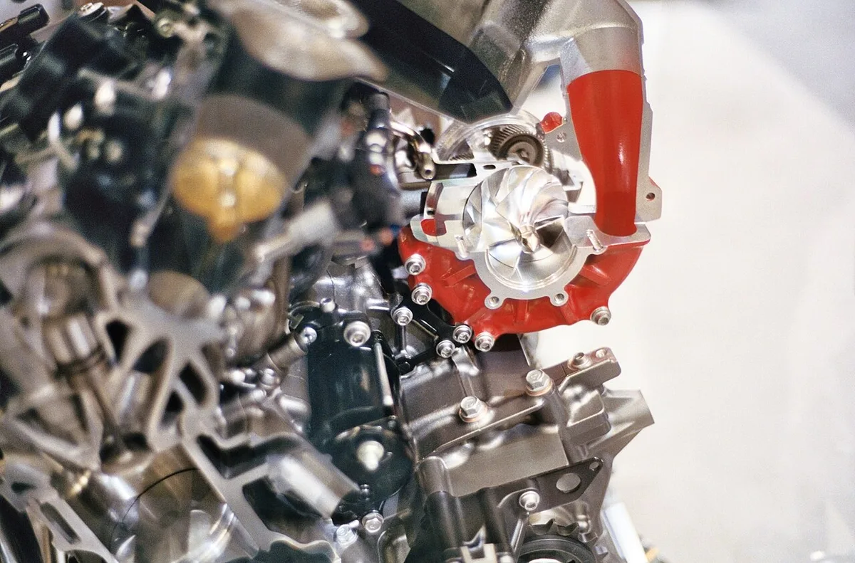
Image source: Wikimedia Commons / Dennis Bratland (CC BY-SA)
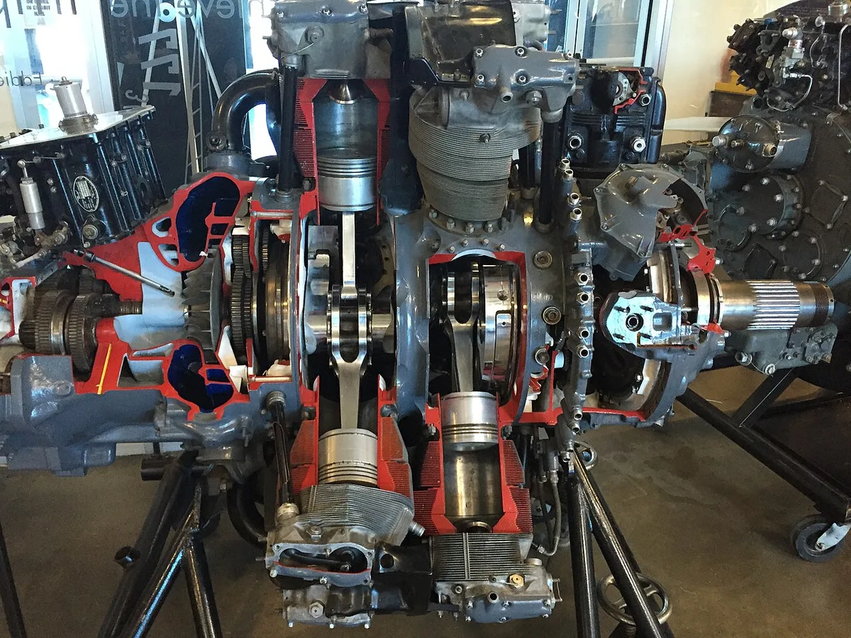
Image source: Wikimedia Commons / Kitplane01 (CC BY-SA)
| Type | What you see inside | Where it usually mounts |
|---|---|---|
| Roots | Two lobes that mesh | On the intake manifold |
| Twin-screw | Rotors that squeeze the air | On the intake manifold |
| Centrifugal | An impeller in a scroll | Low on the front, belt driven |
Around the housing you'll see charge pipes, an intercooler, and a throttle body. The intercooler is the finned core in that pipe path. It cools the air after compression so the charge stays dense.
A bypass valve handles light-load driving. Some kits add a blow-off valve for throttle lift. On a turbo, the turbine sits in the exhaust instead of on a belt.
People comparing the two often set a turbo kit's price beside the blower bracket.
Interpreting Airflow Schematics, Engine Cutaways, and Boost Gauges
Read a schematic in order. Outside air hits the filter. The compressor raises pressure.
The intercooler cools that charge. Then the intake manifold feeds the cylinders.
On a cutaway, study the rotor mesh or the impeller blades. Tight mesh on a Roots or twin-screw unit is what pushes the air. Curved blades on a centrifugal unit fling air outward into the scroll.
Per SAE International, compressor maps plot pressure ratio against airflow. The useful zone sits between surge and choke. You won't see that map in the bay.
You'll see the result on a boost gauge.
| What the gauge shows | What it usually means | What to check |
|---|---|---|
| Vacuum at idle | Bypass is open | Bypass valve and hose |
| Rising psi on throttle | Compressor is working | Belt and charge pipes |
| A spike, then a fall | Leak or a valve dump | Clamps and blow-off valve |
Loose couplers cause a lot of low-boost complaints. Pair the gauge with reading stored fault codes before you replace the blower. Extra cylinder pressure can also push oil past tired rings.
That shows up as oily plug tips.
Step-by-Step Visual Guide to the Supercharging Process
Watch one cycle on the diagram, starting at the crank pulley.
- Watch the crank pulley turn the belt.
- Trace that belt to the supercharger snout.
- Follow compressed air out of the housing.
- Find the intercooler in the charge pipe.
- Continue to the throttle body and the intake manifold.
- Note where fuel joins the denser air.
- See exhaust leave. It does not spin the supercharger.
At cruise the bypass stays open, so you're not forcing full boost. Plant your foot and the bypass closes. Boost then rises with engine speed.
Manufacturer claims for bolt-on kits often start near 50 extra horsepower and climb on a built engine. Centrifugal impellers spin far above crank speed because of a step-up drive inside the nose.
Stay inside what the engine was built for. Leave the knock sensor active. Detonation under boost breaks pistons.
On the exhaust side, sealing exhaust flanges matters more as output rises. On a boosted diesel, bigger fuel injectors are a common way to hold a safe mixture.
Modified engines in the US still have to meet EPA emissions rules. The blower doesn't replace that hardware.
Frequently Asked Questions
Does a supercharger have turbo lag?
No. A belt from the crankshaft spins the compressor whenever the engine runs. There is no exhaust turbine to wait on.
Roots and twin-screw blowers pull hard at low rpm. A centrifugal unit builds more boost as revs rise, but that still is not turbo lag.
Does every supercharged engine need an intercooler?
Most street engines need one because compression heats the air. Hot air is less dense and knocks more easily. The intercooler sits in the charge pipes and cools the air before the manifold.
A few race setups skip it, and heat soak shows up fast.
What boost reading is normal?
Many street superchargers run about 7 to 15 psi under load. At idle you should see vacuum or near zero with the bypass open. A reading that climbs and then falls often means a leaking coupler.
Trust the gauge and the pipe diagram together.
How can you spot a boost leak on a diagram?
Start at the compressor outlet and follow each joint to the manifold. A leak looks like a loose clamp or a split hose. The bypass and blow-off valve are supposed to open.
A cracked charge pipe is not. Soapy water on those joints will bubble if boost is escaping.
