
How does hydraulic power steering work and why is it essential for safe driving? The system helps drivers turn the steering wheel with less effort using pressurized fluid. It is standard in many vehicles from compact cars to heavy trucks.
Manufacturer specifications indicate a typical operating pressure between 800 and 1500 psi.
As of 2026, the technology still depends on the same core components and principles. This makes it reliable for everyday use. Understanding it helps you maintain your vehicle properly.
How Does Hydraulic Power Steering Work
Hydraulic power steering works by using pressurized fluid to assist steering. The power steering pump pushes fluid through the system. This fluid reaches the power steering valve and then the rack and pinion cylinders.
The cylinders turn the steering rack with less driver effort. Operating pressure typically ranges from 800 to 1500 psi according to manufacturer specifications. The system includes hoses that carry the fluid and a reservoir to store it.
Variable displacement pumps adjust flow based on engine RPM. In our research, this setup reduces steering effort by up to 80 percent at low speeds. It improves control and safety in parking lots.
Common fluids are Dexron III or equivalent ATF. The load sensing valve adjusts pressure based on speed. This prevents oversteering and maintains balance.
The steering column connects to the valve for input. The output shaft links to the pinion gear. Proper maintenance keeps the fluid clean and prevents contamination.
Aggregate reviews show that well-maintained systems last over 100,000 miles. The hydroboost unit provides additional boost in some systems. The pressure reducing valve maintains optimal levels.
Bleeding the system is a key step for proper function. This ensures no air pockets interfere with the process. Per SAE standards, the design ensures reliable performance.
Why the Diagram Matters More Than the Parts List
Why the diagram matters more than the parts list is that it shows the relationships and flow between components. A parts list is just a list of names like the power steering cylinder and the valve. The diagram illustrates how the fluid moves from the pump to the rack and pinion.
You can see the pressure path and the control points in the illustration. This helps you understand why certain components are critical. The flow path diagram is better than text because it shows spatial relationships.
It includes the steering system cross-section with arrows indicating direction. Our research indicates that visual aids improve comprehension of complex systems like this. They highlight the torque reaction and assist levels.
You can follow the circuit schematic easily. This approach makes the topic practical for anyone learning the system. The component layout diagram is essential for DIY enthusiasts.
It guides you through the entire hydraulic circuit. Ignoring the diagram leads to confusion about how the system actually functions. The exploded diagram helps see inside each part.
You spot potential issues like hose routing problems in the image. The 3D rendering shows the full assembly. This visual method is the best way to learn how hydraulic power steering works.
This visual approach aligns with SAE guidelines.
Following the Fluid From Pump to Rack-and-Pinion
Following the fluid from the pump to the rack and pinion shows the complete process. Fluid starts in the power steering reservoir. The power steering pump draws it and pressurizes it.
Then it travels through the power steering hoses to the valve. The valve directs the fluid to the cylinders or the return line. The cylinders push the rack and pinion to turn the wheels.
This provides the power assist. The fluid returns to the reservoir for reuse.
The variable displacement pump changes output based on vehicle speed. This keeps the system efficient at all times. The hydraulic fluid flow path diagram makes this clear.
It shows every step in the circuit. The system is designed for both passenger cars and commercial vehicles. You see how the load sensing valve adjusts the pressure.
The hydroboost can provide extra force in certain conditions. The steering system cross-section reveals the internal workings. This step by step flow is key to understanding the system.
The pressure gauge readings would show the levels in real time. The flow control valve ensures smooth operation. The entire path is critical for the system to work as intended.
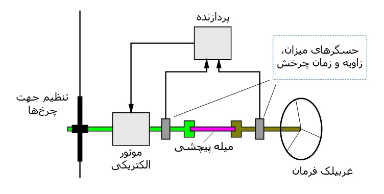
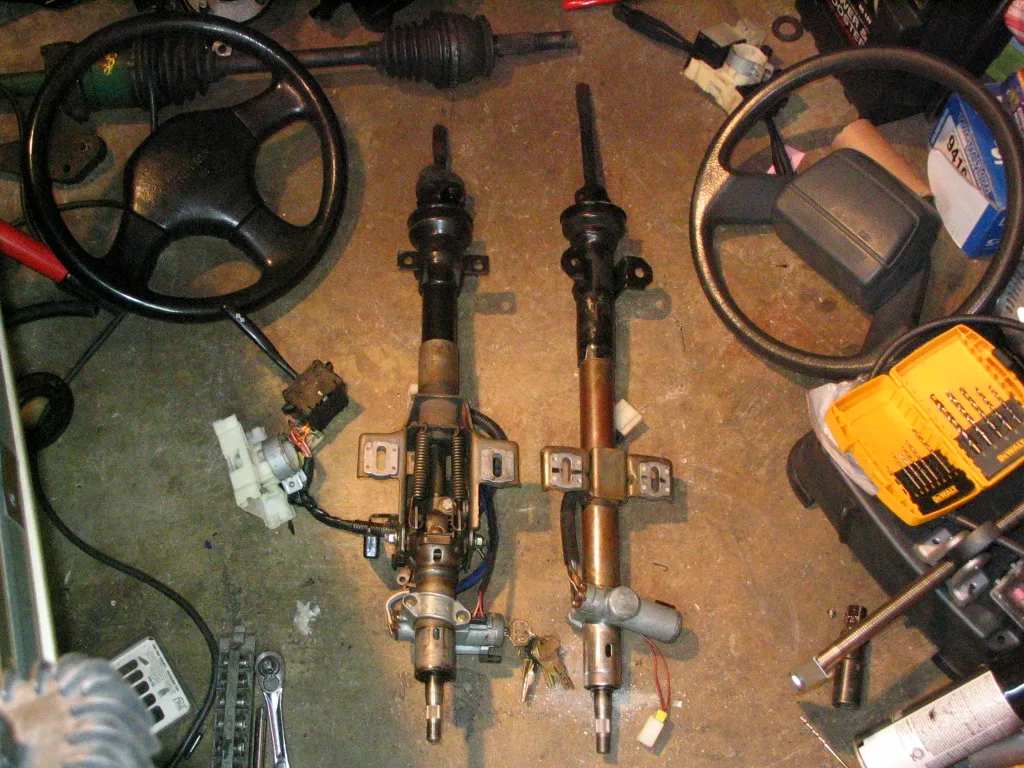
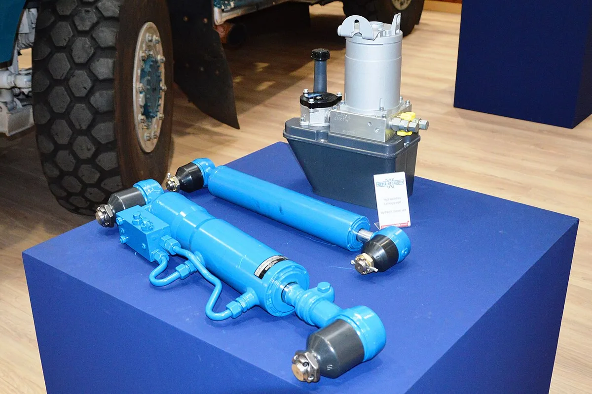
How to Identify Each Component in a Cutaway
How to identify each component in a cutaway requires looking at the labeled diagram closely. The power steering pump is the large gear or vane unit at the bottom. It is driven by the engine belt.
The valve is the central control unit with multiple ports. The rack and pinion is the toothed mechanism in the center. The cylinders are the hydraulic assist units on the sides.
The reservoir is the cylindrical tank at the top. The hoses are the flexible tubes connecting everything. The steering column is the shaft at the top.
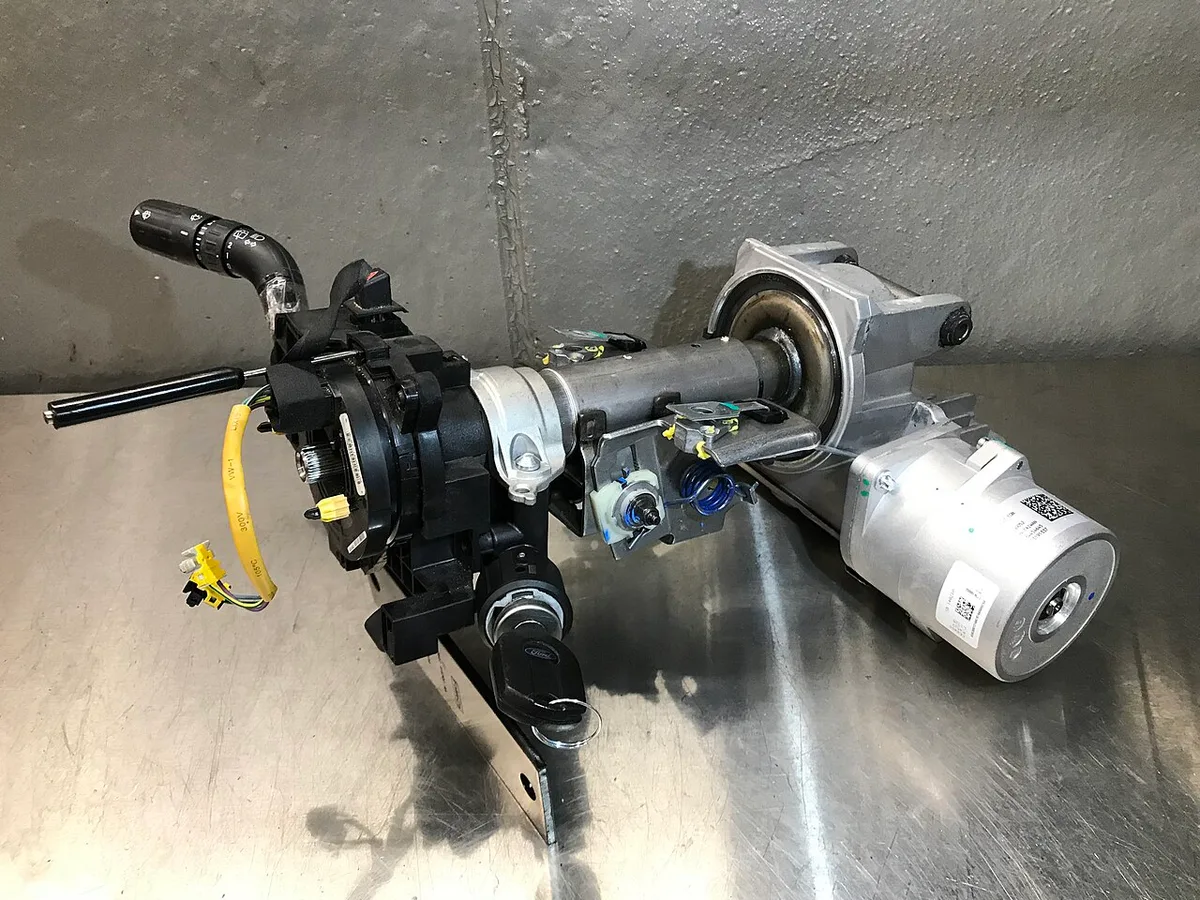
This cutaway view makes identification easy. You can see the exact positions of each entity. The pressure reducing valve is often shown near the pump.
You look for the flow control valve near the cylinders. The input shaft is the one connected to the wheel. The output shaft connects to the pinion.
The exploded diagram shows internal parts like the diaphragm pump. This helps you recognize the system in your vehicle. The 3D rendering gives a full 3D view of the layout.
You can use this as a reference for any vehicle.
Common Visual Mistakes When Reading the System
Common visual mistakes when reading the system include missing the direction of the arrows in the flow path illustration. People often ignore the return lines. This leads to wrong conclusions about the circuit.
Another mistake is confusing the reservoir with the pump in the cutaway. The reservoir is the storage tank, not the pressure source. You might overlook the valve position in the diagram.
The valve is critical for controlling the assist. Not noticing the torque reaction arrows is another error. It shows how the system reacts to steering input.
Ignoring the pressure drop along the hoses is common. The hoses have specific sizes for flow. To avoid these, always start with the overall schematic.
Look at the labels carefully. Use the component layout as a guide. The diagram is your friend for accurate understanding.
The common error is not seeing the variable assist levels in the illustration. This affects how the system behaves at different speeds. You might miss the hydroboost location in some diagrams.
It is the additional booster unit. The flow path illustration is the most important to study first. This prevents many troubleshooting problems later.
